|
NELSON MKII WIND TUNNEL DETAILS HOME | AUTOMOTIVE | BLUEPLANET | ELECTRIC CARS | FORMULA E | ENERGY | INSURANCE | INDEX | SOLAR CARS |
|
|
You would not believe the inane comments we get about small scale wind tunnels. It seems some folk miss the point entirely or are deliberately obtuse. A tunnel of this scale is a handy tool for gauging performance relative to other designs tried at the same scale. It is not a definitive tool. For that you'd need a full size tunnel. The point though is that here you have a tool in you own home/office/workshop where others do not. With such an instrument on your doorstep you can do so much more economically and faster than other conceptual designers. You will learn a lot just from making it. The steerage is invaluable compared to the time it takes to build the unit. You can add to the accuracy of measurements and analysis by going digital, linking a computer to the strain gauge tunnel outputs. |
|
|
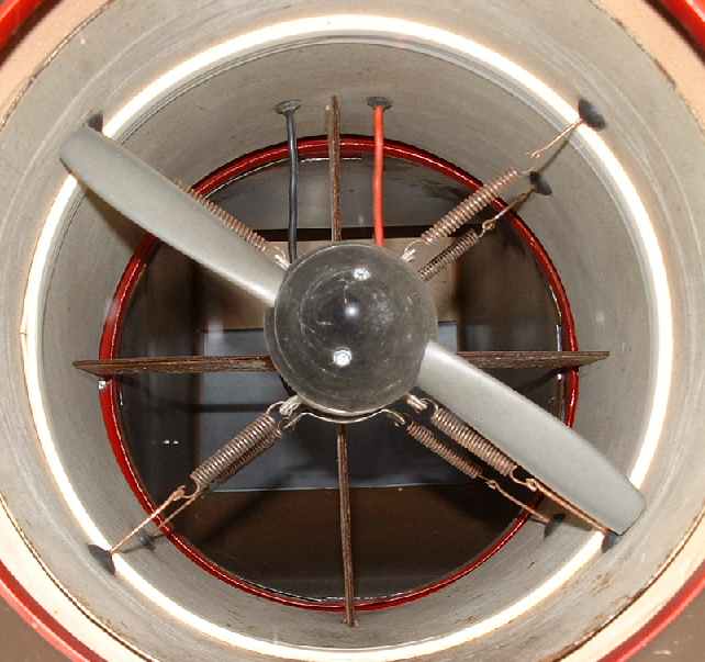
Take a look at the propeller and motor to the left. The 1hp motor is mounted on eight springs to reduce vibration, rubber damped. The whole fan module is then positioned on rubber mounts, which in turn channel vibration through a weighted plywood frame. The net effect is to pass the vibration through materials with different natural frequencies, so acting as a vibration filter, much like coils and capacitors are used to filter out unwanted frequencies in Hi Fi speaker systems. Lead weights are also employed to give mass to the mild steel base frame unit.
|
Spring mounted 1hp fan motor
|
|
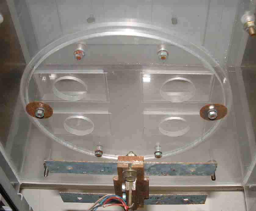
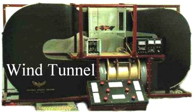
Air temperature and wind speed were also monitored and smoke could be trailed over models to visualize airflow, to highlight problem areas. This tunnel could fit comfortably on an office desk. It measured just 60" x 40" x 15". Being a closed circuit design it was not unbearably noisy in operation.
The plexiglas chamber provided superb all round visibility, which is so important.
Strain gauges provided measurement of drag, lift and down-force. A rotating table was incorporated so that vehicle models could be tested in side wind conditions. |
Plexiglas test chamber viewed from underneath
|
|
|
|
|
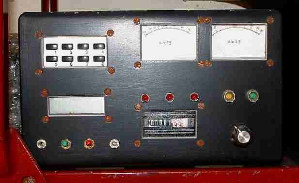
It is necessary to have variable speed control of the main fan unit. The control panel above shows temperature gauge, amp and volt meters for the main motor and hours run meter. There are other switches for smoke trails, etc.
An ordinary domestic light dimmer switch was used to vary the voltage supplied to a mains transformer, which in turn supplied 12 volts to the fan motor. |
Wind tunnel control panel |
|
|
|
|
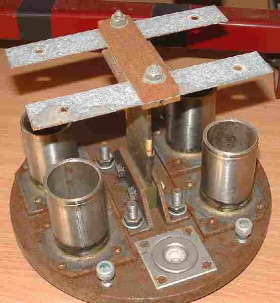
A wind tunnel is a complex piece of engineering. The Wright Brothers were the first inventors to use such a tool to compile lift and drag tables for various wing shapes. It is much more difficult to design a balance to measure lift and down-force on each wheel of a vehicle. When working at such a small scale, accuracy of measurement is essential. Fortunately, electronics come to the rescue, with compensated amplifiers providing multiplication of movement (lift/downforce) up to ten thousand.
|
Five element balance with oil damping units (slightly the worse for wear) |
|
|
|
|
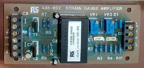
Five of the above RS strain gauge amplifiers gave separate channels of information to provide a range of measurements to include drag, lift and down-force for each wheel.
Each amplifier is fed information from a bridge of four foil resistors bonded to each element of the balance, two on each side. There are five elements to the balance, consequently, you will need quite a few (20) strain gauges and some patience during the epoxy bonding and positioning. The marking out must be exceptionally accurate for consistent results.
|
RS strain gauge amplifier
|
|
|
|
|
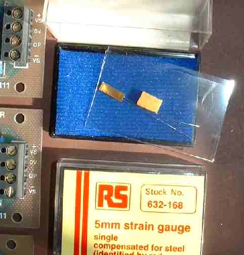
The components used in the making of this tunnel, were not exactly cheap if you are on a small budget, but more importantly, with suppliers such as Radio Spares (RS) they at least are widely available to amateur scientists and enthusiasts, such as myself.
Plan out any project and cost it well in advance, or spend will spiral.
|
Single laser cut 5mm strain gauge - foil resistor
|
|
|
|
|
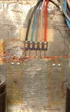
Here is the close up wiring of one of the five steel elements against which bend fractionally stretched one side of the plate (increasing resistance) and compressed (lowered resistance) the other side of the plate. The sensitivity (voltage) multiplication effect of such a bridge is well known.
The completed assembly is coated in silicone for environmental protection.
The build of this wind tunnel took approximately 2 months from start to conclusion. |
Strain gauges bonded to steel element - 2 on each side to form a wheat sheaf bridge
|
|
|
|
|
MODEL MAKING STAGES
Steps 1. Mark out your plywood and cut formers Step 2. Assemble plywood formers Step 3. Fill formers with foam and shape Step 4. Coat foam plug with plaster Step 5. Sand, add detail mouldings and prime Step 6. Paint finished model
LOADING-SERVO | CARTRIDGE | MOTORS | JOYSTICK-CAR WIND-TUNNEL | WIND TUNNEL DETAILS
This is the kind of result you can expect from your wind tunnel - a super slippery 350+ mph electric streamliner. This particular car is charged by solar power, making it probably the world's fastest solar powered electric land speed record car. She also has battery cartridge exchange built in, for instant EV refueling.
LINKS
http://www.grc.nasa.gov/WWW/k-12/airplane/tunnel1.html http://www.roboticsschool.ethz.ch/sfly-summerschool/programme/1.1-Leutenegger-Airplanes_Aerodynamics_Performance.pdf http://www.landracing.com/forum/index.php?topic=862.235;wap2 http://www.geversaircraft.com/wt/wtsmall.htm
|
|
|
The content of this website is copyright © and design copyright 1991 and 2013 Electrick Publications. All rights reserved. The bluebird logo & names Bluebird and Blue Max are registered trademarks. The BE2 and BE3 vehicle configurations are registered designs ®. All other trademarks are hereby acknowledged. Max Energy Ltd is an environmental educational charity working for world peace.
|
|