|
|||||||||
|
MOTORS and TRANSMISSION
Without a motor, you have no car. Without an efficient motor, you have less chance of winning a competition. But, you also have to design your drivetrain, so that your motor operates at it's peak efficiency, which means keeping it spinning, keeping the revolutions up. You also have to decide which motor and controller to buy on cost.
The drive train in a solar car is very different from that of a conventional car. For our purposes, the drive train will consist of the electric motor and the means by which the motor's power is transmitted to the wheel causing the vehicle to move. Due to the low amount of power generated (less than 5 hp) usually only one wheel in the rear of the car is driven by the electric motor.
Unless you have limitless funds, cut gears are a luxury and indeed, may waste energy. Chains and belts are by far the simplest approach, chains actually being more efficient than belts - around 95%. A gearbox as such may also be unnecessary, since your car will be running at its optimal speed almost all of the time. Most solar car events don't include hill climbs for that reason, although you may encounter some gentle inclines.
In the past, the most common type was the direct drive transmission where the motor is connected to the wheel through a chain or belt with a single gear reduction. This is a reliable and easily maintained transmission if special care is taken when aligning the components. Efficiencies above 80% can be achieved when designed properly.
A few teams have used variable ratio belt drives to transmit power to the wheel. The gear ratio changes as the speed of the motor increases. This gives the motor more starting torque at lower speeds, but still allows the car to run efficiently at higher speeds. Variable belt drives require precise alignment and careful setup to work efficiently.
Depending on your wheel and tyre size, you may need to reduce (gear down) the motor revolutions from 5,000 - 3,0000 to around 500 - 800 rpm at the wheel. Multiply the wheel diameter by 3.143 to give distance per revolution, then multiply that distance by RPM until you have the target speed. You can work backwards from this figure, or work forward from the overall drag (including rolling resistance) at the target speed, to obtain the motor output you need.
There are several variations of three basic types of transmissions used in solar cars.
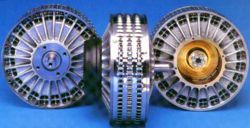
Since 1995 when a few teams implemented hub motor designs in their solar cars, the popularity of the transmission-free drive has soared. A hub motor eliminates the need for any external transmission because the motor shaft is connected directly to the wheel hub. This greatly increases the efficiency of the drive train and reduces the number of moving parts necessary to drive the wheel. A hub motor uses low rpm to account for the lack of gear reduction, which tends to drop their efficiency slightly, but they still can achieve efficiencies in excess of 95%.
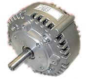
There are no restrictions on the type of motor used in a solar car. They are generally rated between 2 and 5 hp. The most common type of motor used in solar cars is the dual-winding DC brushless. A DC brushless motor is fairly lightweight and can reach efficiencies of 98% at their rated rpm, however they are quite a bit more expensive then a typical brush type DC motor.
Flemings Leftt Hand Rule
Since multi-geared transmissions are seldom used in solar cars, the dual-winding motor is sometimes used as an electronic transmission. Switching between the dual windings changes the speed rating of the motor. The low speed windings provide high torque for starting and passing, while the high speed windings have higher efficiencies and are best for cruising (normal running).
Similar to the power electronics, most teams purchase off the shelf motors, but there are solar cars with custom built or self built motors.
Also, some motor and controller setups allow for regenerative braking, which allows the solar car to put energy back into the batteries when going downhill. For the beginning team, DC brush motors would be sufficient to get a solar car up and running. Another variable in choosing a motor is how much power it has. We have found that there is little need to have more than 5hp continuous power output on our motors.
There are two manufacturers who supply most teams with motors and controllers: Solectria and Advanced DC Motors. Many college teams buy their motors from Solectria, but Advanced DC Motors have less expensive motors. Controllers usually drive a particular motor. Once you choose the motor that suits your needs, the same vendor would most likely have a matching controller.
BASIC MOTOR PRINCIPLES
All motors require two magnetic fields, one produced by the stationary part of the motor (the stator, or field), and one by the rotating part (the rotor, or armature). These are produced either by a winding of coils carrying a current, or by permanent magnets. If the field is a coil of wire, this may be connected in a variety of ways, which produces different motor characteristics.
The basic law of a motor, the reason why they rotate, is governed by Fleming’s left hand rule. This tells you the direction of the force on a wire that is carrying current when it is in a magnetic field.
Force acting on wire carrying current, obeying the left hand rule
If we now bend the wire round in a loop, and place it in a magnetic field caused by two permanent magnets, we have the situation shown in the diagram below. Here, both sides of the wire loop will have a force on them, trying to make the wire loop rotate. The current is applied to the loop through the commutator, which is shown as two pieces of metal formed into a ring in the figure. Current is applied to the commutator by stationary graphite blocks, called brushes, which rub against the commutator ring.
The loop will continue to rotate anticlockwise (as we see it in the figure) until it is vertical. At this point, the stationary brushes won't be applying current around the loop any more because they will be contacting the gap between the commutator segments, but the inertia of the loop keeps it going a little more, until the DC supply reconnects to the commutator segments, and the current then goes around the loop in the opposite direction. The force though is still in the same direction, and the loop continues to rotate.
This is how DC motors work. In a real motor, there are many wire loops (windings) all at varying angles around a solid iron core. Each loop has its own pair of commutator segments.This block of core and wire loops is called the rotor because it rotates, or the armature.
The fixed magnets in the diagram above generating the field may be replaced by electromagnets which are generally more powerful. The elctromagnets are supplied by the same power supply as the armature winding, either in series (series connected) or in parallel (shunt connected) as shown in the diagram below.
If permanent magnets are used, the motor is said to be a permanent magnet (PM) motor. DC motors can also have permanent magnets in the armature, and electromagnets for the stator coils. In this case, the stator windings must be switched in some way to make the permanent magnets in the rotor follow them to cause rotation. This connection is less common for small motors.
Series, shunt and permanent magnet windings
There may be more than just the two fixed magnets, called poles. In some motors there may be four poles (imagine one more coming from above and one more from below in the figure). There will always be an even number of poles, since there is an N pole for every S pole, and in the equations governing the motor, the number of poles is often quoted as p, the number of pole pairs. These magnets are called the stator because they are stationary, and the electromagnet coils are called the field windings because they generate the magnetic field.
The supply is connected to the commutator segments through graphite brushes. These are held in little sockets with a spring behind them, so the brush is pushed onto the segments. This guarantees a good electrical connection (although there will be a fraction of an Ohm resistance across them). Eventually, these brushes wear down completely. If you get the motors from a scrap yard, the brushes may need replacing. New brushes should be available from automotive spares shops.
Back EMF
In the same way that a wire carrying a current in a magnetic field has a force acted upon it (left hand rule), conversely a moving wire in a magnetic field gets a voltage induced across it. This is called Lenz's law. In a motor, the consequence of this is that the supply voltage makes the rotor rotate, and the rotor generates a ‘back emf’ or reverse voltage, which nearly matches the supply voltage when the motor is rotating but not driving anything.
The resistance of the coils of wire that make up the field and armature are normally very low. So you would think that the motor would take a very large current (current = voltage ÷ resistance). However this back emf means that there is actually only a small voltage across the resistance of the coils, because the back emf, ea, is nearly as large as the supply voltage, Vt. Some typical values for a 900Watt starter motor are: Rt = 0.041 Ohms, Vt = 12V, ea = 11.9v, so the motor current is 2.4 Amps. When
a load is put on the motor, the speed drops, and so the back emf drops, and
so the current drawn from the battery will increase.
Torque
The torque produced by a permanent magnet or shunt wound motor is given by the equation: T = kfΦia The torque produced by a series motor is given by the equation T = kfia2 where kf is a constant for the motor, and ia is the current, and Φ is the field strength. A series wound motor generates its field from the same armature current, so Φ increases as the motor draws current. Therefore the torque is proportional to the square of the current. This means that doubling the current that we put through a series wound motor quadruples the torque. This is a distinct advantage of series wound motors.
Current
When you read a DC motor datasheet, it will sometimes (if you are lucky!) have some characteristic graphs that tell you how the motor is likely to respond. These mostly have Load Torque as the bottom x-axis, and plot motor current, speed, power, and sometimes efficiency as they relate to the load torque. Sometimes they may have motor current on the bottom axis instead of load toruqe. In this case the graphs are still almost the same shape because the motor current is almost directly proportional to the load torque in all DC motors. Different types of field windings produce different shapes for these graphs. For a permanent magnet or shunt wound DC motor, the current drawn by the motor increases linearly with load torque:
Notice that the line does not intersect the (0Nm / 0A) origin point. The zero torque point intersects at 25 Amps for this motor (an Iskra 900W starter motor). This means that the motor will not even start to turn until it is pulling 25 Amps! Speed
For all DC motors, the speed is nearly proportional to the supply voltage, except for the effect of the armature resistance:
From this graph, and the equation, it can be seen that the speed of a series motor with no load torque will rise to infinity! This doesn't happen in practice because there is always a little load torque because due to friction in the motor. It can also be seen that as a little load torque is added to a series wound motor, the speed drops off very quickly to start with, but then drops off less quickly.
With both motor field types, eventually, when the load torque becomes even larger, say when a stronger robot is pushing us backwards, the motor speed becomes negative (the motor starts rotating backwards).
In practice, the speed line for a PM or shunt wound motor may not be a straight due to frictional loads which are not linearly dependant on speed. The torque speed graph of a DC motor when it is being driven by a speed controller with current limiting can be found in the speed controllers section.
Power and efficiency
The power a motor is taking from the battery is P = [V - Ea]ia or P = [V - Ea]2/Ra
The power the motor is putting into the load is P = TΩ When the motor is running with no extra load other than its friction, then the load torque is zero, and so the output power is zero. The input power is small also because the back emf is almost equal to the supply voltage. The only power drawn from the battery is driving the loss torque: Ploss = Tloss Ω
When the motor is driving such a large torque that it has stalled, then the back emf is zero, and the input power is very large: P = V2/Ra
and the output power is zero because the speed is zero. The efficiency of the motor is defined as the amount of mechanical power you are getting out of the motor divided by the amount of electrical input power you are putting in, so:
power_out efficiency = ----------- power_in
The efficiency can also be plotted against load torque. Here is the efficiency graph for an Iskra shunt wound starter motor:
Just because the maximum efficiency is at around 1Nm doesn't mean that you have to run the motor at that torque though!
Characteristic graphs for some motors
Most of the graphs presented above were based on example values. Let's look at the characteristic graphs for some real motors: Iskra
12 Volt 900 Watt shunt wound starter motor Lynch
(LEMCO) motors
Selecting DC motors
Sizing a DC motor to accurately meet a set of requirements can be a thankless task. Having to choose between brush-type or brushless motors can complicate the selection. Even experienced designers may sometimes overlook critical motor parameters and find problems after the system is up and running.
Experts, however, use an expedient procedure to properly size and select dc motors. This procedure is based upon an accurate definition of the target system parameters and designer experience. Solar racers may not be so lucky as to have a limitless choice of motors to begin with.
Dc motor parameters:
Fortunately, several motor parameters are the same for both brush-type and brushless dc motors. One of these is motor constant: Km. It is important but widely overlooked. It is used during motor sizing because it is a figure of merit of the motor power-to-torque ratio.
A candidate motor with the required Km value or greater is selected from a catalog. The motor is only a candidate at this point because other factors must be determined. As the design selection progresses, some trade-offs typically take place. For example, the motor must also satisfy physical size and inertia requirements.
Winding resistance is a major factor in motor selection because it seriously affects Km. Winding resistance and motor current produce power loss in the form of heat and motor temperature rise (TPR). These losses are also referred to as I2R losses and directly degrade motor efficiency.
Most motor windings are copper wire which has a positive temperature coefficient. A winding temperature rise from 25 to 155°C increases wire resistance as much as 50%. Likewise, a proportional decrease in resistance occurs for temperature drops.
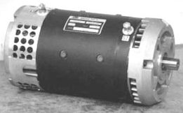
Solectria dc motor
Core losses:
Hysteresis and eddy currents in the core also make motor temperature rise. At high speeds, these losses can produce as much or more heat than I2R losses.
Core losses depend primarily on the motor design. Design factors affecting those losses include lamination thickness, flux densities in the armature, and frequencies generated in the core that depend upon the number of poles and speed. Catalog specifications may not include core loss data, so designers must measure it by testing several sample motors. The data may also be available directly from the motor manufacturer.
Ambient temperature is the third most important factor determining motor temperature rise. A motor having a winding temperature rating of 155°C and operating in an ambient temperature of 100°C has only a 55°C allowable temperature rise. Core losses and I2R losses quickly cut the 55°C margin under load. An ideal room ambient temperature of 25°C, by comparison, allows a 130°C temperature rise.
Use of heat sinks and air or fluid cooling moderates the temperature rise value considerably. The TPR rating of the motor per watt of input power, °C/W, is usually in the catalog or data sheet for unmounted motors. The TPR for the same motor, but mounted, TPR´ can be 25% of the unmounted value. A conservative designer could ignore the reduced TPR in his calculations. But he would specify a motor much larger and more expensive than necessary.
Magnet properties:
Dc motors use a variety of permanent-magnet materials. Early designs employed ceramic or ferrite and AlNiCo magnets. These materials are still widely applied, however, in automobiles and other areas where low cost as well as reliability is important. Newer designs use rare-earth samarium-cobalt and neodymium magnets.
Most magnets have stable magnetic properties within the normal operating temperature range of the motor. But some magnets have a higher temperature coefficient than others. High temperature-coefficient magnets may become too weak if operated at high temperatures for extended periods. Depending on the magnetic material and slope of the motor's magnetic circuit, torque degradation may result over a wide temperature range. Ceramic or ferrite magnets lose about 0.13% / °C of their remanence above 25°C, while rare earth and AlNiCo may lose only 0.03% / °C. But this loss is generally reversible if the temperature is kept within the motor rating. Colder temperatures are seldom a problem. Since the coefficient curve is linear, magnets are stronger at lower temperatures.
Some grades of rare-earth magnets are more sensitive to temperature than others. Magnets in the neodymium family may have irreversible magnetic losses under wide temperature changes. These magnets have the highest maximum-energy product (MEP), a figure of merit, of any commercial magnet now available. High MEP comes at a premium and should not be lost to temperature extremes. Neodymium magnets are continually being improved with lower temperature coefficients to make them as stable as other rare-earth grades.
Peak loads applied to AlNiCo and ceramic dc motors can degrade their magnetic properties. AlNiCo motors have a peak current rating which usually corresponds to a point above the knee of the B/H curve. Current exceeding this rating, caused by either a current spike or a constant dc input, are over the knee and cause permanent demagnetization. A demagnetized AlNiCo motor may only provide 50 to 60% of its original torque. Fortunately, rare-earth magnets are not as sensitive to demagnetization as AlNiCo and ceramic.
Advanced DC Motors .5 H.P. (.37kw) to 35H.P. (26kw)
Brushless versus brush-type:
Designers planning to integrate a dc motor into a system usually work from a development specification. Constraints and limits in the specifications will largely determine whether a brush-type or a brushless motor is acceptable, based on the qualities of each.
Brush-type motors are generally used below 5,000 rpm. The actual operating speed depends upon the commutator diameter and brush material. Brush life decreases with higher commutator surface speed. Surface speed for silver-graphite brushes is usually below 650 fpm while paliney brushes are limited to only 50 fpm.
Other factors which limit brush motor life include commutator bar-to-bar voltage, brush current density, and power at the brush-commutator interface. High current and power at the brushes and commutator bar-to-bar voltage (not terminal voltage) greatly exceeding 15 Vdc produce excessive arcing. Arcing erodes brushes and commutators; wear accelerates once erosion begins.
On the other hand, electronic drives for brush motors are usually much simpler than for comparably sized brushless motors. No position sensors or electronics are required for commutation. But these components are mandatory for brushless operation. Unless used in a servocontrol loop, brush-type dc motors need no electronics other than a power source.
Since brushless dc motors have no commutators or brushes, brush and commutator arcing does not limit speed. Brushless dc motors are better suited for applications needing a wide speed range. Speeds from a stalled condition to more than 60,000 rpm are not unusual.
Brushless motors replace mechanical commutators with electronic switching. Brushless dc motor controllers require a position feedback signal from a sensor inside the motor. The sensor ensures that excitation to the electromagnetic armature field always leads the permanent-magnet field to produce torque. Power transistors drive the armature windings at a specified motor current and voltage level.
Most brushless dc motors are constructed with an outer-wound stationary armature and a rotor consisting of permanent magnets. Rotors of this type are small and have low inertias. And heat transfers more efficiently from the wound armature to ambient air in this configuration because heat dissipates from the armature core to the outer metallic housing, not conducted through the shaft like most brush-type configurations.
Motor sizing:
Motor sizing takes into account all the above motor parameters and specifications. Also, the motor inertia and load must be defined for both transient and steady-state conditions. These inertia are critical since torque during acceleration exceeds torque at constant speed.
Two examples explain the sizing of dc motors for typical applications. The first example considers the selection and sizing of a brush-type dc motor. The second concerns a sterile outer-space environment requiring a brushless dc motor.
Briggs & Stratton M7 ETek motor
SPEED CONTROLLERS
Introduction
The purpose of a motor speed controller is to take a signal representing the demanded speed, and to drive a motor at that speed. The controller may or may not actually measure the speed of the motor. If it does, it is called a Feedback Speed Controller or Closed Loop Speed Controller, if not it is called an Open Loop Speed Controller. Feedback speed control is better, but more complicated, and may not be required for a simple robot design.
Motors come in a variety of forms, and the speed controller's motor drive output will be different dependent on these forms. The speed controller presented here is designed to drive a simple cheap starter motor from a car, which can be purchased from any scrap yard. These motors are generally series wound, which means to reverse them, they must be altered slightly.
Curtis PMW controller
Theory of DC motor speed control
The speed of a DC motor is directly proportional to the supply voltage, so if we reduce the supply voltage from 12 Volts to 6 Volts, the motor will run at half the speed. How can this be achieved when the battery is fixed at 12 Volts?
The speed controller works by varying the average voltage sent to the motor. It could do this by simply adjusting the voltage sent to the motor, but this is quite inefficient to do. A better way is to switch the motor's supply on and off very quickly. If the switching is fast enough, the motor doesn't notice it, it only notices the average effect.
When you watch a film in the cinema, or the television, what you are actually seeing is a series of fixed pictures, which change rapidly enough that your eyes just see the average effect - movement. Your brain fills in the gaps to give an average effect. Now imagine a light bulb with a switch. When you close the switch, the bulb goes on and is at full brightness, say 100 Watts. When you open the switch it goes off (0 Watts).
Now if you close the switch for a fraction of a second, then open it for the same amount of time, the filament won't have time to cool down and heat up, and you will just get an average glow of 50 Watts. This is how lamp dimmers work, and the same principle is used by speed controllers to drive a motor. When the switch is closed, the motor sees 12 Volts, and when it is open it sees 0 Volts. If the switch is open for the same amount of time as it is closed, the motor will see an average of 6 Volts, and will run more slowly accordingly.
As the amount of time that the voltage is on increases compared with the amount of time that it is off, the average speed of the motor increases.
This on-off switching is performed by power MOSFETs. A MOSFET (Metal-Oxide-Semiconductor Field Effect Transistor) is a device that can turn very large currents on and off under the control of a low signal level voltage.
The time that it takes a motor to speed up and slow down under switching conditions is dependant on the inertia of the rotor (basically how heavy it is), and how much friction and load torque there is. The graph below shows the speed of a motor that is being turned on and off fairly slowly:
You can see that the average speed is around 150, although it varies quite a bit. If the supply voltage is switched fast enough, it won’t have time to change speed much, and the speed will be quite steady. This is the principle of switch mode speed control. Thus the speed is set by PWM – Pulse Width Modulation.
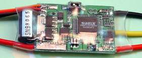
Miniature speed controller and brushless DC motor for radio controlled flight
PWM frequency
The frequency of the resulting PWM signal is dependant on the frequency of the ramp waveform. What frequency do we want? This is not a simple question. Some pros and cons are:
TIRES AND HUBS
One of the best tires are the Bridgestone Ecopia tires made for solar cars. They are very thin and operate at over one hundred pounds/inch pressure. Unfortunately, they need to be mounted on specially made wheels and require custom made hubs. On the positive side, these tires and wheels are very light.
Some college teams have experimented with bicycle tires but report limited success. Bicycle tires, rims and spokes are not designed for the lateral forces placed on them by non-tilting vehicles weighing several hundred pounds). Motorcycle tires tend to be too heavy and have more rolling resistance, although there may be high pressure tires with low resistance that I don't know about. If you know of any or are a manufacturer making such, please let me know.
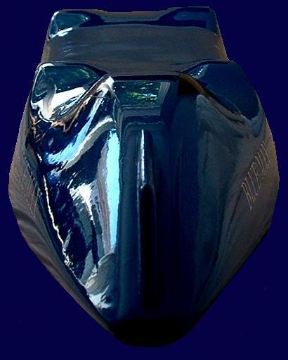
The Blueplanet Ecostar in the only land speed record streamliner to be solar powered. It uses DC pancake motors driving all four wheels to produce 400Kw and an expected speed of around 350+ mph. Click on the car to read more.
LINKS:
Theory
of starter motors. Quite a good page. Controlling
voltage spikes (motor suppression). SGS Thomson Acrobat document. Using
car windscreen wiper motors
Power electronics: Diac Triac Thyristor, General overview, Miscellaneous topics, Motor speed control, Power control, Power supplies, Power supply topics, SMPS
Circuits for motor control, automatization, Power control Control tutorials mathlab PID, frequency respons, digital control, motor speed AC motor speed control with IGT pdf file AC - DC motor speed control with MOSFETs pdf file Bidirectional VF Control of Single and 3-Phase Induction Motors Using the PIC16F72 Closed loop control open loop identification (step function response), closed loop : P and PI control of a DC motor, a tip Controlling 3-Phase AC Induction Motors Using the PIC18F4431 Controlling a small DC motor pdf file Controlling motors and transformers with dimmers DC motor control pdf file DC motor speed control PWM, program written in C DC motor speed control L298, LMD18200, UDN2998 DC motor speed control using Pulse Width Modulation MAX620 Démarrages des moteurs asynchrones triphasés à cage en Français, SWF file Determining MOSFET driver needs for motor drive applications MOSFET, IGBT, stepper motor control, power switching, pdf file Driving DC motors pdf file Electronic control of direct current motors first quadrant speed control, two-quadrant control-armature reversal, two-quadrant control -two converters, two-quadrant control - two converters with circulating current, two-quadrant control with positive torque, four-quadrant control, Electronic Control of Alternating Current Motors FREQUENCY
CONTROLLED AC MOTOR DRIVE The squirrel cage induction motor is the
electrical motor Gradateurs en Français IMPROVED UNIVERSAL MOTOR DRIVE triac control, IGBT control, ST6210, pdf file Modulation de largeur d'impulsion en Français, pdf file MOSFET/IGBT DRIVERS theory and applications, pdf file Motion control systems pdf file Motor control overview pdf file Motor control and power electronics ppt file Motor Control Sensor Feedback Circuits Motoren en frequentieregelaars in Dutch, pdf file Motor power control motor power control, TRIAC, UJT, impulstransformator, phase control Motor sturing omzetters en sensoren, in Dutch, pdf file Omzetters, sturen motoren in Dutch Power electronics and drives control of electrical drives, switched-mode converters, two-quadrant converters, four-quadrant converters, bipolar switching, unipolar switching, PWM Pulse Width Modulated (PWM) AC drives pdf file Réglage de la vitesse des moteurs asynchrones triphasés en Français Réglage de vitesse des moteurs asynchrones triphasés en Français, pdf file SENSORLESS MOTOR DRIVE WITH THE ST6220 MCU AND TRIAC pdf file Solid state control for bi-directional motors pdf file Speed controllers speed control of AC and DC motors Speed controllers principle of switch mode speed control, H bridge, MOSFET, encoder Step motor drive technology (pdf-format) Universal motor control Universal motor control: the universal motor is a rotating electric machine similar to a DC motor but designed to operate either from direct current or single-phase alternating current, ... Variable-switched-reluctance motors VSR motors Variateur de vitesse en Français Variation de vitesse de la machine à courant continu zip file, en Français
CONTROLLERS: 4QD
Part
1
|
|||||||||
|
EDUCATION | SOLAR CAR RACING TEAMS | SOLAR CAR RACING EVENTS | FILMS | MUSIC |
|||||||||
|
The
content of this website is copyright © and design copyright 1991 and
2019 Electrick Publications. All rights reserved. The bluebird
logo |